Most sections are under active development. Page outlines are in
place so the structure is clear, but detailed content will land over the
next few release cycles. One section is already complete:
Hardware Acceleration read it for a concrete
sense of the depth and style the rest of the docs are headed toward.
Sections
Getting Started set up a development environment and run a first reference deployment.
Contributing how to file issues, propose RFCs, and submit pull requests.
1 - Getting Started
Set up a development environment and run a first reference deployment.
Coming soon. The quick-start walkthrough is being written alongside
the first public reference-stack release. Until then, the
Hardware Acceleration section has a
complete operator guide that exercises most of the platform.
Planned content:
Prerequisites Linux host, Kubernetes cluster, CLI tools.
Installing the reference stack with Helm and kpt.
Deploying a minimal CU/DU pair.
Verifying the deployment.
Pointers to the Architecture, Deployment, and Hardware Acceleration sections for going deeper.
2 - Architecture
High-level architectural design of the OCUDU 5G gNB layer responsibilities, inter-layer correlation, deployment topology, and the execution and async fabric that binds them.
1. What OCUDU is
OCUDU is a full 3GPP/O-RAN compliant 5G NR gNB implemented in C++17/C++20.
It terminates every standardized RAN interface Uu toward the UE (via
PHY/OFH/RU), F1-C/F1-U between CU and DU, E1 between CU-CP and
CU-UP, N2/N3 toward the 5G Core (AMF/UPF), Xn between peer gNBs,
and E2 toward the near-RT RIC. The codebase is functionally
disaggregated so the same binaries can run co-located (gnb) or split
across machines (cu_cp + cu_up + du, with optional du_low for an
O-RAN Split-6 PHY).
Three architectural ideas run top-to-bottom through the code:
Single logical entity → independent functional units. Every layer
(CU-CP, CU-UP, DU-High, DU-Low, RU) is an owned object tree with a
well-defined public interface and internal adapter notifiers. Layers
never call each other directly; they call adapters, which the assembly
code wires to concrete callees at construction time. This is why the
same DU-High object can be wired to a local in-process CU-CP (via
f1c_local_connector) or to a remote CU-CP (via SCTP) without
recompilation.
Async-procedure first. All multi-step control-plane flows (UE
setup, handover, PDU session setup, E1/F1 bearer ops) are modeled as
async_task<R> C++ coroutines composed with CORO_AWAIT_VALUE(...).
The procedure classes live under routines/ and procedures/
subdirectories of every protocol layer.
Per-entity executors. Concurrency is expressed as task dispatch
to named task_executor instances: per-cell, per-UE-UL, per-UE-DL,
per-crypto-worker, per-gateway-IO. Serialization is achieved either
by a single-threaded worker or a strand over a shared pool never
by coarse locks.
2. High-level topology
flowchart LR
    UE((UE))
    AMF[/AMF/]
    UPF[/UPF/]
    RIC[/near-RT RIC/]
    PEER[/Peer gNB/]

    subgraph gNB
      direction LR
      subgraph CU[Centralized Unit]
        CUCP[CU-CP<br/>RRC · NGAP · XnAP · NRPPa]
        CUUP[CU-UP<br/>PDCP · SDAP · GTP-U]
      end
      subgraph DU[Distributed Unit]
        DUH[DU-High<br/>F1AP · MAC · RLC · Scheduler]
        DUL[DU-Low<br/>Upper PHY]
      end
      RU[Radio Unit<br/>Lower PHY / OFH-WG4]
    end

    UE  <-- Uu --> RU
    RU  <-- OFH/SDR --> DUL
    DUL <-- FAPI-like PDU API --> DUH
    DUH <-- F1-C sig --> CUCP
    DUH <-- F1-U data --> CUUP
    CUCP <-- E1 --> CUUP
    CUCP <-- N2 SCTP --> AMF
    CUUP <-- N3 GTP-U --> UPF
    CUCP <-- Xn --> PEER
    CUCP <-- E2 --> RIC
    DUH  <-- E2 --> RIC
    CUUP <-- E2 --> RIC
Each functional block is a standalone compilation unit under lib/,
wrapped by an application unit under apps/units/ that adds YAML
config, logging registration, metrics, and PCAP plumbing. The gnb
binary composes all three app units in one process; the split binaries
compose only their own unit and use SCTP/UDP gateways for cross-entity
links.
CU-CP is the RRC/NGAP termination point and the orchestrator of every
per-UE control procedure. The owning class is cu_cp_impl
(lib/cu_cp/cu_cp_impl.h); it aggregates four repositories one each
for DUs, CU-UPs, AMFs, and Xn peers plus a ue_manager, a
mobility_manager, a cell_meas_manager, and an nrppa_entity.
Interfaces terminated. NGAP (TS 38.413) on N2, F1AP (TS 38.473) on
F1-C, E1AP (TS 38.463) on E1, XnAP (TS 38.423 / 37.483) on Xn-C, plus
NRPPa for positioning and E2AP for near-RT RIC. Each protocol has its
own state machine in its lib/ directory and exposes an adapter
interface back into cu_cp_impl.
UE lifecycle. The canonical Initial UE Message flow runs like this:
DU sends F1AP Initial UL RRC Message Transfer → du_processor_impl
allocates a cu_cp_ue via ue_manager::add_ue() and binds F1AP/RRC
adapters.
NGAP forwards a NAS Initial UE Message to the AMF and establishes
an NGAP UE context.
AMF responds with Initial Context Setup Request, which launches
initial_context_setup_routine a coroutine that sequentially
awaits: Security Mode Command on RRC → F1AP UE Context Setup → UE
Capability Transfer → nested pdu_session_resource_setup_routine
(E1AP Bearer Context Setup → F1AP UE Context Modification → RRC
Reconfiguration).
Every step is a CORO_AWAIT_VALUE on the next async sub-procedure, so
the routine reads like synchronous pseudocode but never blocks a thread.
Concurrency model. CU-CP runs on a single cu_cp_executor. A
CU-CP-wide FIFO (cu_cp_common_task_scheduler) orders global tasks;
each UE has its own FIFO (ue_task_scheduler_impl) so per-UE procedures
serialize without blocking unrelated UEs. AMF connections get their own
FIFO per NGAP instance. The result is fine-grained serialization without
a single global lock.
Mobility.mobility_manager inspects measurement reports from
cell_meas_manager and dispatches to one of three paths: intra-CU,
inter-CU via Xn, or inter-CU via NG (AMF-routed). Conditional Handover
has its own state machine in cu_cp_ue_cho_context. All three paths
share a common coroutine skeleton under lib/cu_cp/routines/.
CU-UP terminates N3 (GTP-U to UPF) and F1-U (NR-U to DU) and implements
the PDCP/SDAP layers in between. The E1AP interface receives Bearer
Context Setup/Modify/Release from CU-CP and materializes the per-UE
object tree.
flowchart LR
    subgraph UE_CTX[Per-UE context]
      direction TB
      PDUs[pdu_session] --> DRB[drb_context]
      DRB --> QF[qos_flow_context]
    end
    subgraph N3[N3  UPF]
      NG[gtpu_tunnel_ngu_rx/tx]
    end
    subgraph F1U[F1-U  DU]
      FB[f1u_bearer_impl<br/>NR-U DDDS]
    end
    NG -->|TEID demux| SDAPT[sdap_entity_tx<br/>QFI mark]
    SDAPT --> PDCPT[pdcp_entity_tx<br/>cipher · integrity · SN]
    PDCPT --> FB
    FB --> PDCPR[pdcp_entity_rx<br/>decipher · reorder]
    PDCPR --> SDAPR[sdap_entity_rx<br/>QFI strip]
    SDAPR --> NG
Object hierarchy. A pdu_session owns its N3 GTP-U tunnel, an SDAP
entity, and a map of drb_context entries. Each DRB owns a PDCP entity,
an F1-U CU-UP bearer, and a map of qos_flow_context entries. TEIDs are
allocated from n3_teid_allocator and f1u_teid_allocator pools.
PDCP. TX maintains TX_NEXT, TX_TRANS_CRYPTO, TX_REORD_CRYPTO,
TX_TRANS, TX_NEXT_ACK (TS 38.323 §7.1). Ciphering and integrity run
on a parallel crypto_executor pool; custom state variables track
in-flight crypto operations so PDUs can be emitted in the correct order
even when parallel workers finish out-of-sequence. RX implements the
reordering window and the t-Reordering timer per TS 38.323 §5.2.2.2.
F1-U / NR-U.f1u_bearer_impl consumes NR-U data delivery status
messages from the DU and feeds handle_transmit_notification() /
handle_delivery_notification() into PDCP TX, which advances
TX_NEXT_ACK and releases discard-timer slots. The DU also reports
desired buffer size; PDCP TX uses it as a back-pressure signal for
early drop.
Concurrency. Every UE is assigned four executors by the
ue_executor_mapper: ctrl (E1AP), ul_pdu (F1-U RX), dl_pdu (N3
RX), crypto (pooled). GTP-U demux per-TEID dispatches PDUs onto the
owning session’s dl_pdu executor in batches, so a single UE’s data
path is serialized while different UEs run in parallel on different
workers.
DU-High is orchestrated by du_manager_impl, which owns the cell and UE
context repositories and reacts to three event streams: F1AP procedures
from CU-CP (UE Context Setup/Modify/Release per TS 38.473), MAC
indications (UL-CCCH from Msg3, C-RNTI CE on handover access), and
operator reconfig from the app-level configurator.
MAC split.mac_dl_processor per cell runs on a high-priority
slot_ind_executor; on each slot it calls the scheduler’s
get_slot_result() and then pulls PDUs from RLC TX entities for each
granted logical channel. mac_ul_processor receives Rx_Data
indications, routes by C-RNTI via rnti_manager (lock-free atomic
allocator starting at MIN_CRNTI = 0x4601, TS 38.321 §7.1),
demultiplexes MAC subPDUs, feeds BSR/PHR to the scheduler, and hands
LCID payloads to RLC RX.
RLC. Three modes exist: TM (SRB0, passthrough), UM (SRBs, no ARQ),
AM (DRBs, full ARQ). AM TX tracks TX_NEXT_ACK, TX_NEXT, POLL_SN
plus byte/PDU poll counters; AM RX runs a reassembly window keyed on
RX_NEXT with a t-Reassembly timer that generates STATUS PDUs on gap
or timeout (TS 38.322 §5.2, §5.3.3). The SDU queue between PDCP and RLC
is a lock-free SPSC this is the reason the slot-indication hot path
can pull PDUs without blocking on RLC state updates happening on the UE
executor.
F1AP-DU.f1ap_du_impl decodes F1AP ASN.1, dispatches to
per-procedure coroutines (F1 Setup, UE Context Setup/Modify/Release,
DL/UL RRC Message Transfer, Paging), and forwards RRC containers to the
right RLC SRB via adapters in
lib/du/du_high/du_manager/du_ue/du_ue_adapters.h.
Adapter pattern. DU-High never calls F1AP or PDCP directly; it holds
a set of small adapter classes (f1c_rx_sdu_rlc_adapter,
rlc_rx_rrc_sdu_adapter, mac_sdu_tx_builder, mac_sdu_rx_notifier)
whose targets are set at UE-creation time. This is what lets the same
DU-High binary work with an in-process F1-C connector or a remote SCTP
F1-C without code changes.
6. MAC scheduler
Source: lib/scheduler/.
The scheduler is the most intricate subsystem. scheduler_impl owns one
cell_scheduler per cell and one ue_scheduler per carrier-aggregation
cell group this split is deliberate: cell-wide resources (SSB,
PRACH, SI, CSI-RS, PUCCH format resources) are per-cell state, while UE
data state must be shared across CA component carriers.
flowchart TD
    SI[scheduler_impl::slot_indication] --> CS[cell_scheduler::run_slot]
    CS --> RG[cell_resource_allocator<br/>ring buffer, ~16 slots]
    CS --> SSB[ssb_sch]
    CS --> CSIRS[csi_rs_sch]
    CS --> SIS[si_sch<br/>SIB1 + SI msgs]
    CS --> PR[prach_sch]
    CS --> RA[ra_scheduler<br/>RAR · Msg3 · Msg4]
    CS --> PG[paging_sch]
    CS --> US[ue_scheduler::run_slot]
    US --> EV[event_manager<br/>config · feedback]
    US --> UCI[uci_scheduler<br/>SR · CSI PUCCH]
    US --> SRS[srs_scheduler]
    US --> FB[fallback_sched<br/>SRB0]
    US --> INTER[inter_slice_scheduler]
    INTER --> INTRA[intra_slice_scheduler]
    INTRA --> POL[scheduler_policy<br/>time_rr · time_qos]
Resource grid.cell_resource_allocator is a circular buffer of
per-slot cell_slot_resource_allocator entries, sized for
SCHEDULER_MAX_K0 / K1 / K2 look-ahead. Each entry contains symbol
× CRB bitmaps for DL and UL and the accumulated sched_result handed
to MAC.
Per-UE state split.ue is cell-group-wide (logical channels, DRX,
timing advance). ue_cell is per-cell (active BWP, HARQ entities, MCS
calculator, power controllers, fallback flag). A UE in CA has one ue
and several ue_cell views indexed by serving cell index (PCell = 0).
Slicing. Two layers: inter_slice_scheduler ranks RAN slices by
SLA/min-PRB/max-PRB each slot and produces DL/UL candidates;
intra_slice_scheduler then applies a pluggable scheduler_policy
(time-domain Round-Robin or Proportional-Fair implemented in
lib/scheduler/policy/) to rank UEs within a slice and allocate
PDSCH/PUSCH. Fallback UEs on SRB0 use a dedicated
ue_fallback_scheduler instead.
HARQ. Each UE has 8 DL + 8 UL HARQ processes per serving cell
(cell_harq_manager), tracked by NDI toggling, a bounded
max_nof_harq_retxs, and a slot_timeout for missed ACKs.
Config safety.sched_config_manager converts add/update/remove UE
requests into ue_config_update_event objects applied at slot
boundaries by the event manager. Config never changes mid-slot.
Concurrency. One slot runs on one thread per cell; in CA,
cell_group_mutex is taken only when the cell group has more than one
cell, so single-cell deployments pay zero lock cost.
DU-Low implements only the Upper PHYlib/du/du_low/README.md
states the DU-Low is O-RAN Split 7.2x aligned, with the Lower PHY pushed
into the RU. The radio_unit interface (include/ocudu/ru/ru.h) has
three concrete implementations: OFH-RU (O-RAN fronthaul,
production), SDR-RU (direct baseband via UHD/ZMQ, which pulls Lower
PHY back into the host), and Dummy-RU (loopback for testing).
Upper PHY. Drives LDPC (base-graph 1/2 per TS 38.212 §5.3.2, with
AVX2/AVX512/NEON kernels), polar coding for control, CRC (LUT or
CLMUL), scrambling (Gold sequence per TS 38.211 §5.2.1), modulation
mapping up to 256QAM. Channels are objects: pdsch_processor,
pdcch_processor, ssb_processor, csi_rs_generator,
pusch_processor, pucch_processor, prach_detector. For
hardware-offload of LDPC, see
Hardware Acceleration → Intel ACC100 (LDPC).
Lower PHY (when present via SDR path). OFDM modulator/demodulator
with pluggable DFT backends FFTW, AMD FFTZ/AOCL, ARM Performance
Library, generic Cooley-Tukey. CP length selection follows TS 38.211;
phase compensation is precomputed via LUT.
Open Fronthaul (WG4 CUS).ofh_sector encapsulates one OFH logical
antenna array. The transmitter encodes C-plane section types (1 DL/UL
data, 3 PRACH), the U-plane packer compresses IQ via Block Floating
Point (O-RAN.WG4.CUS Annex A.1.2, with SIMD kernels), and eCPRI framing
produces Ethernet-ready packets. The receiver reverses this, with an
rx_window_checker that rejects packets outside the RX window and a
symbol reorderer that re-sequences out-of-order U-plane traffic. Timing
is driven by realtime_timing_worker against CLOCK_REALTIME
(PTP-disciplined in production) it emits OTA symbol boundaries to
which transmitter, receiver, and DU-Low subscribe.
DPDK integration. Ethernet TX/RX under lib/ofh/ethernet/dpdk/ uses
busy-polling on dedicated lcores, selected by CPU affinity in the
worker manager.
Async.async_task<R> is a C++20 stackless coroutine;
async_procedure<R> is a non-coroutine fallback with the same awaitable
shape. event_signal and manual_event are the awaitable primitives
used to park a coroutine until PHY/peer response arrives.
protocol_transaction_manager wraps the transaction-ID + timeout
pattern every ASN.1 protocol needs.
Executors. The task_executor interface has a zoo of
implementations: inline_task_executor (test),
general_task_worker_executor (one thread, policy-driven queue),
priority_task_worker_executor (multi-priority), strand_executor
(serialize over a shared pool using atomic job count),
sync_task_executor (block until done). All tasks are
unique_function<void(), 64> a 64-byte small-buffer-optimized
closure, no heap allocation for typical lambdas.
Queues. Lock-free SPSC (rigtorp) and MPMC (rigtorp) underpin the
data path; locking MPSC/MPMC variants exist for cold paths. The SPSC
RLC SDU queue is the reason the slot-indication pull path is
non-blocking.
byte_buffer. A segmented, reference-counted zero-copy buffer backed
by a thread-local segment pool. Slicing produces views without copying;
every data-path handoff moves buffers by reference-count bump.
Timers.timer_manager is a flat tick-driven timer service
tick() is called once per ms and expired callbacks are dispatched to
the per-timer executor. async_wait_for() wraps a timer as an
awaitable, which is how PDCP t-Reordering, RLC t-PollRetransmit, and RA
contention-resolution timers integrate with the coroutine model.
Gateways.sctp_network_server_impl / sctp_network_client_impl
for N2/F1-C/E1/Xn; udp_network_gateway_impl for N3/F1-U; io_broker
(epoll) manages socket FDs and dispatches events to executors. Every
gateway takes an executor reference so RX callbacks run where the
protocol layer expects them.
Logging & tracing.ocudulog is an async log framework with
per-channel levels, pluggable sinks (file/stdout/syslog/UDP), and
formatter classes. l1_dl_tracer, l1_ul_tracer, l2_tracer emit
compile-time-gated binary trace events for latency analysis; Tracy
integration is optional.
9. Deployment topologies and wiring
OCUDU compiles four binaries gnb, cu_cp, cu_up, du plus
du_low for Split-6. The same lib/ code powers all of them; the
difference is which app units the binary composes and which gateway
factories it picks.
flowchart LR
    subgraph gnb[Co-located gnb binary]
      CC1[CU-CP] -- local --- CU1[CU-UP]
      CC1 -- local --- D1[DU]
      CU1 -- local --- D1
    end
    subgraph split[Split CU/DU]
      CC2[cu_cp binary] -- SCTP/F1-C --- D2[du binary]
      CC2 -- SCTP/E1 --- CU2[cu_up binary]
      CU2 -- UDP/F1-U --- D2
    end
Selection rule.gnb.cpp instantiates f1c_local_connector,
e1_local_connector, f1u_local_connector (zero-copy in-process
queues). The split binaries instantiate SCTP servers/clients and a UDP
gateway instead. The application units and lib/ code are identical in
both paths only the connector factory differs. Recent commits added
full SCTP socket-parameter plumbing (RTO, heartbeat, retransmission)
into F1 and E1 config so operators can tune transport per deployment.
App units (apps/units/) o_cu_cp, o_cu_up, flexible_o_du
provide a uniform interface (application_unit) covering YAML schema
registration, logger setup, worker-manager contribution (CPU affinity,
NUMA, pool sizes), PCAP plumbing, and metrics aggregation. This is how
a single gnb binary cleanly composes three functional entities with
shared workers and a single buffer pool.
Worker manager and buffer pool. One worker_manager sizes and pins
every executor thread per YAML-declared affinities. One
buffer_pool_manager provides the byte_buffer segment pool that every
layer uses no layer allocates its own heap in the data path.
Remote control and metrics. An optional uWebSockets-backed
remote_server exposes JSON commands (UE dump, cell start/stop,
metrics query). A central metrics_manager aggregates producers from
every layer and fans them out to configurable sinks (log, stdout, JSON,
file) on a periodic tick.
10. Layer correlation summary
Plane
CU-CP
CU-UP
DU-High
DU-Low / RU
L3 / NAS
RRC, NGAP, XnAP, NRPPa
L2 Ctrl
F1AP-CU, E1AP-CU
E1AP-CU-UP
F1AP-DU, MAC Ctrl
L2 Data
PDCP, SDAP, GTP-U, F1-U CU
RLC, MAC DL/UL, Sched
L1
FAPI-like PDU API
Upper PHY (DU-Low), Lower PHY + OFH (RU)
Transport
SCTP (N2/F1-C/E1/Xn)
UDP (N3/F1-U)
SCTP (F1-C), UDP (F1-U)
eCPRI/Ethernet (OFH) or UHD/ZMQ (SDR)
The control plane forms a chain CU-CP → DU-High via F1-C, with E1 as a
side-link to CU-UP for bearer context. The user plane forms an
independent pipe UPF ↔ CU-UP ↔ DU-High ↔ RU entirely outside CU-CP’s hot
path. The coroutine-based procedure framework cuts across every
control-plane layer uniformly, so a flow like PDU Session Setup reads
as a single linear routine even though it straddles NGAP, E1AP, F1AP,
and RRC.
How to propose an architectural change via the RFC process:
Contributing.
3 - Hardware Acceleration
Offload CPU-heavy upper-PHY stages to vRAN accelerator cards for lower latency, higher throughput, and reduced host CPU.
OCUDU India supports offloading CPU-heavy stages of the upper-PHY from the
host to dedicated vRAN accelerators. The goal is better latency and
throughput on the same hardware budget, with the freedom to fall back to
a pure-software path when no accelerator is available.
Design principles
Software parity. The HW and SW paths implement the same interfaces;
no functional difference observable from MAC or above.
Configuration-driven. Choose path via DU YAML at startup. No code
changes, no runtime toggling.
Unified metrics. Every enqueue/dequeue on the HW path emits the
same metric fields the SW path emits. A/B comparisons use one log format.
Batched dispatch. Operations are accumulated per-TB and submitted to
the accelerator as a single burst, amortising DPDK per-call cost.
On-device state. HARQ soft-buffer data stays on the accelerator
between transmissions; the host tracks only context lifecycle.
High-PRB-count cells (80–100 MHz) where software LDPC becomes the
upper-PHY bottleneck.
Multi-cell hosts where freeing CPU on the upper-PHY increases cell
density per server.
Tail-latency-sensitive deployments LDPC decode tail latency
compresses substantially on hardware.
What to read next
First time enabling HWACC? Start with the ACC100 guide
it covers prerequisites, kernel/VFIO setup, YAML, build flags, and a
deployment checklist.
Already running HWACC and want to understand the numbers? Jump to the
benchmark results for the A/B comparison.
Adding a new accelerator backend? See the
contributing guide for how to file an RFC.
3.1 - Intel ACC100 LDPC offload
Offload LDPC encoding (PDSCH) and decoding (PUSCH) to Intel ACC100 vRAN accelerator cards via DPDK BBDEV, with full upper-PHY metrics instrumentation for side-by-side comparison with the software-AVX-512 path.
Scope: hardware-accelerated LDPC encoding (PDSCH) and decoding (PUSCH)
on Intel ACC100 vRAN accelerator cards, with full upper-PHY metrics
instrumentation so operators can directly compare CPU-software and
HW-offload performance in production logs.
Introduced in commit:aa6db7d066
Highlights
LDPC offload for both PDSCH and PUSCH the most CPU-heavy channel-coding
steps move off the host and onto the accelerator.
Configuration-driven enable or disable via the DU YAML; no code changes.
Unified metrics the same per-block PHY metric fields populate whether
LDPC runs in software (AVX-512) or on the accelerator, enabling direct
side-by-side comparison from one log format.
Measured gains on real traffic significantly lower PUSCH decode
latency, tighter tail latency, higher processor throughput, and reduced
upper-PHY uplink CPU (see §7).
1. Prerequisites
1.1 Hardware
Intel ACC100 PCIe card, SR-IOV capable; at least one VF exposed to the host.
x86-64 CPU with AVX2 (AVX-512 recommended for the software-fallback path).
≥ 2 GB of 2 MiB hugepages.
PCIe slot on the same NUMA node as the upper-PHY worker cores.
1.2 Software
Component
Minimum version
Notes
DPDK
22.11
Tested with 25.11; ACC100 PMD (baseband_acc) required.
# Kernel boot parameters (then update-grub + reboot):intel_iommu=on iommu=pt hugepagesz=2M hugepages=1024# Hugepage mount if not done by distro:echo1024| sudo tee /sys/kernel/mm/hugepages/hugepages-2048kB/nr_hugepages
# Load VFIO modules:sudo modprobe vfio-pci
echo1| sudo tee /sys/module/vfio_pci/parameters/enable_sriov # if kernel-builtin# Create one SR-IOV VF and bind it to vfio-pci:echo1| sudo tee /sys/bus/pci/devices/<ACC100_PF_BDF>/sriov_numvfs
sudo dpdk-devbind.py --bind=vfio-pci <ACC100_VF_BDF>
# Start pf_bb_config holding the PF group open with a VF token.# The token (UUID) is required in the DU's EAL args.sudo /opt/pf-bb-config/pf_bb_config ACC100 \
-c /opt/pf-bb-config/acc100/acc100_config_vf_5g.cfg \
-v <UUID> &
After setup, dpdk-test-bbdev should enumerate the VF as intel_acc100_vf.
2. Architecture overview
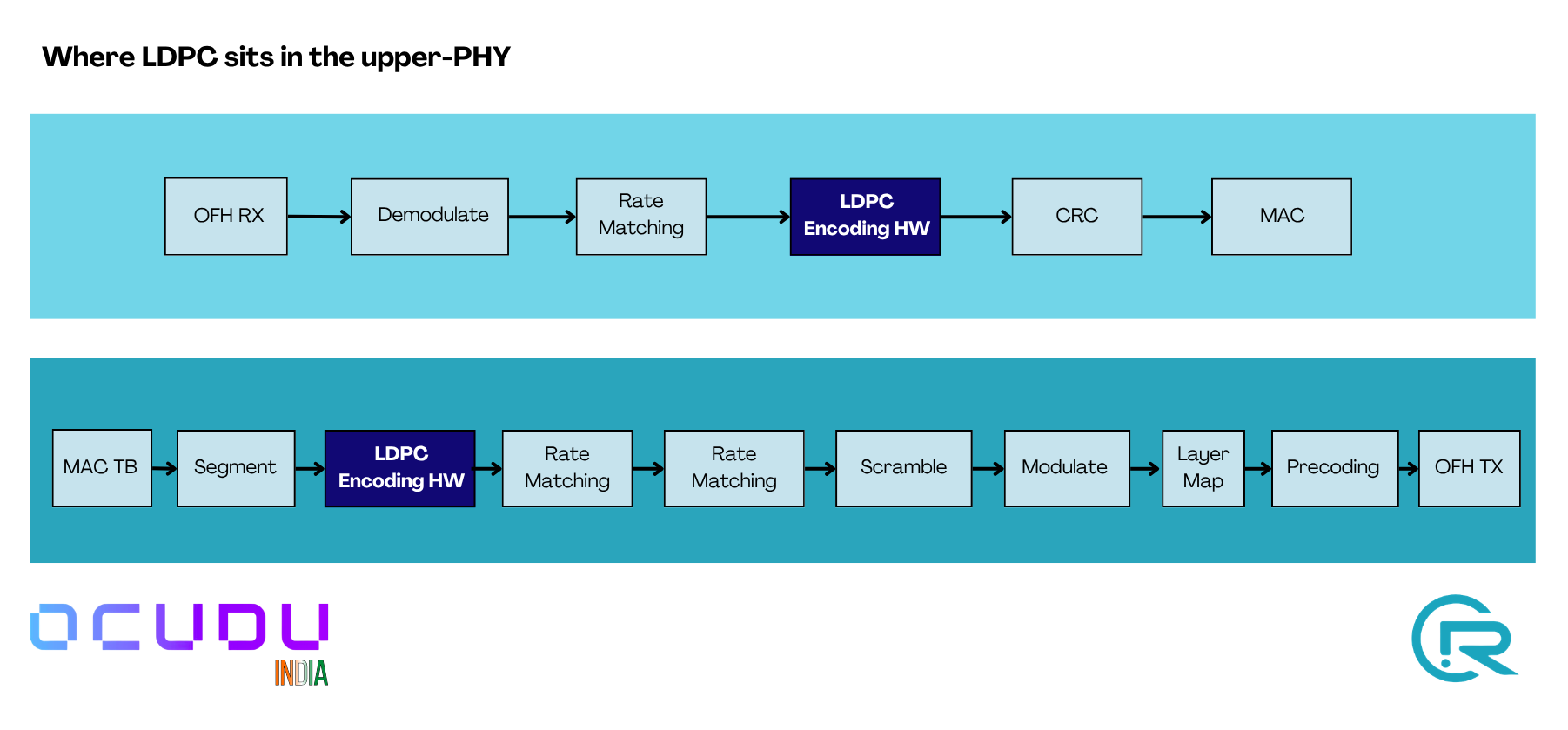
2.1 Where LDPC sits in the upper-PHY
LDPC encode (PDSCH) and LDPC decode (PUSCH) are the two steps this
feature accelerates. On the software path they are AVX2/AVX-512 kernels; on
the HW path they become batched DPDK BBDEV operations dispatched to the
ACC100. Everything else in the chain stays on the CPU.
UL and DL pipelines through the upper-PHY. The LDPC stages (dark blue) run on the ACC100; all other stages stay on CPU.
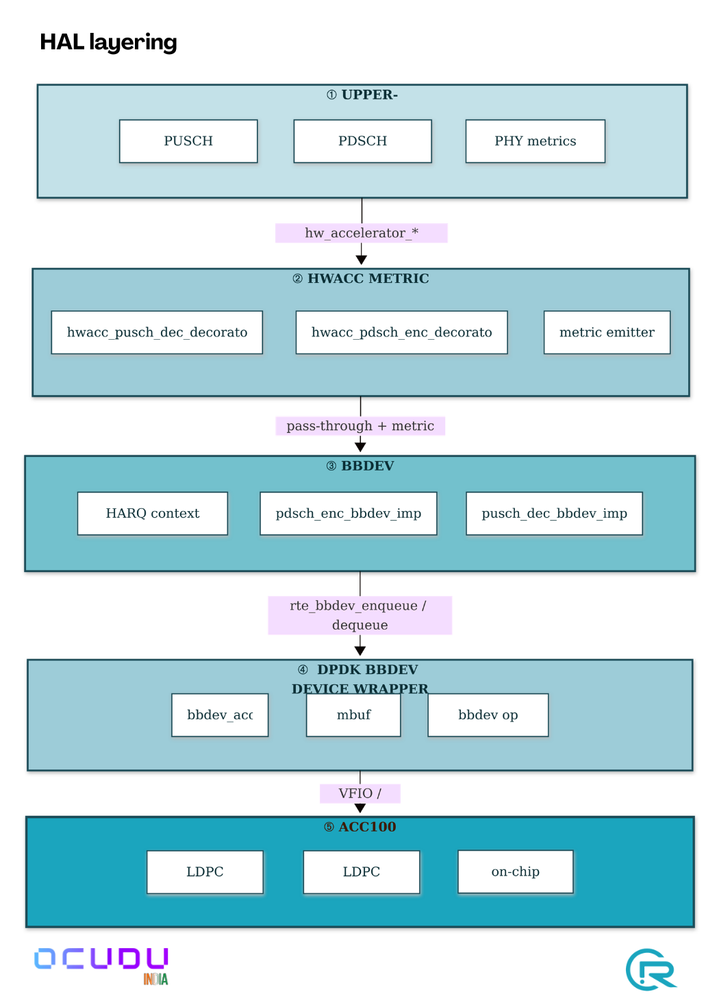
2.2 HAL layering
The upper-PHY factory checks for a hardware accelerator factory at
construction. If present, the HW path is built; otherwise the software
AVX-512 path is used. The choice is made once at startup from the YAML
there is no runtime toggling.
Five-layer HAL from the upper-PHY down to the ACC100 silicon. Each layer's interface to the one below is labelled.
3. Implementation summary
The integration is implemented as a hardware-abstraction layer that plugs
into the existing upper-PHY factory pattern. Four things are worth knowing:
Batching. Encode and decode ops are accumulated in a per-instance
buffer and submitted to the accelerator as a single burst on the first
dequeue call of each transport block. This amortises the DPDK per-call
cost across all code blocks of the TB.
Shared pools. The HAL factory owns one set of DPDK mbuf and op
mempools for all encoder and decoder instances the upper-PHY creates.
Pool size scales automatically with the total queue count across
allowlisted accelerators.
On-chip HARQ. Soft data for HARQ combining stays on the accelerator
between transmissions, addressed by a CB-indexed offset. The host tracks
only the lifecycle of each context entry, not the soft data itself.
Unified metrics. A thin decorator wraps the HW accelerator interface,
times each enqueue–dequeue pair, and emits the same metric events the
software path does. The existing upper-PHY aggregator consumes both
sources transparently.
A handful of ACC100 silicon quirks are handled internally by the HAL (input
byte-alignment, a single-CB transport-block special case, a per-op E-limit
guard, a long-session HARQ-context wrap-around). These require no action
from the operator.
4. Configuration
Enable ACC100 offload in the DU YAML:
hal:eal_args:"--lcores (0-1)@(0-17) --file-prefix=ocudu_gnb --no-telemetry
-a <OFH_NIC_VF_BDF>
-a <ACC100_VF_BDF>
--vfio-vf-token=<PF_BB_CONFIG_UUID>
--iova-mode=pa"bbdev_hwacc:hwacc_type:"acc100"id:0pdsch_enc:nof_hwacc:4cb_mode:truededicated_queue:truepusch_dec:nof_hwacc:4force_local_harq:falsededicated_queue:true
Notes:
nof_hwacc for single-cell deployments, 2–4 is sufficient; for
multi-cell or heavy-load setups, 8–16. Setting higher than the
upper-PHY’s concurrency limits is wasteful.
--iova-mode=pa is recommended; the va mode is known to interact
poorly with some NIC drivers in DPDK 25.11.
The VFIO-VF token must match the UUID passed to pf_bb_config -v.
If pf_bb_config is restarted, update the YAML.
Warning: the configured maximum PDSCH concurrency ... is overridden by the
         number of PDSCH encoder hardware accelerated functions (N)
Warning: the configured maximum PUSCH and SRS concurrency ... is overridden
         by the number of PUSCH decoder hardware accelerated functions (N)
The same fields populate for both the CPU-software and ACC100-HW paths,
enabling side-by-side A/B comparison from a single log format.
7. Results
7.1 Test environment
Item
Value
Host
Single-socket x86_64, 18 cores, AVX-512 capable
OS / DPDK
Linux 5.15 / DPDK 25.11
pf_bb_config
24.03
ACC100
1 PF + 1 VF bound to vfio-pci
OFH NIC
iavf VF for 7.2-split RU
UE workload
Real UE + iperf3 DL/UL + 2 min video streaming + 2 speed tests
Cell
100 MHz TDD, 30 kHz SCS, 4T4R, band n78, 256-QAM max
All measurements taken with the same physical UE and RU; only the gNB
binary differs between the two rows (AVX-512 vs ACC100).
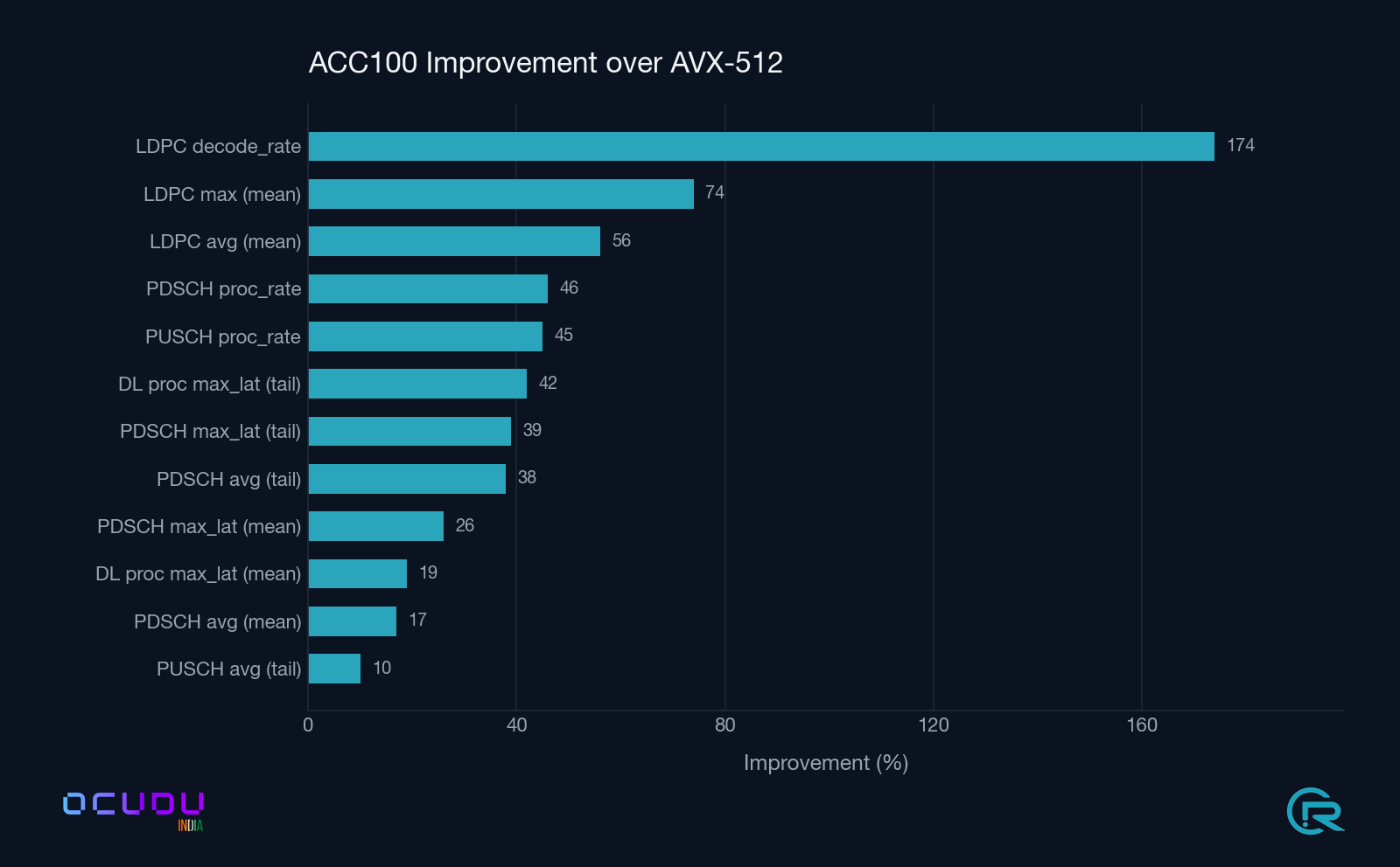
Summary ACC100 percentage improvement over AVX-512 across all measured upper-PHY metrics. LDPC decode throughput leads the board at +174 %.
7.2 End-to-end upper-PHY A/B
Mean / max over ~175 one-second metric windows each.
Metric
AVX-512 (mean / max)
ACC100 (mean / max)
ACC100 Δ
DL processing max_latency
114.9 / 330.2 µs
99.7 / 206.4 µs
−13 % mean, −37 % tail
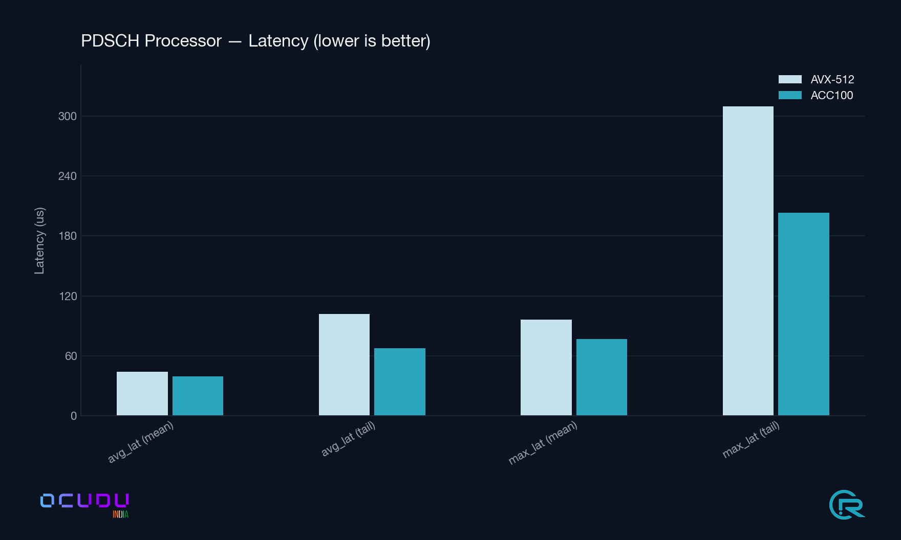
PDSCH Processor avg_latency
44.0 / 101.7 µs
39.3 / 67.8 µs
−11 % mean, −33 % tail
PDSCH Processor proc_rate
198.0 Mbps
310.1 Mbps
+57 %
PDSCH Processor max_latency
96.5 / 309.8 µs
76.6 / 203.2 µs
−21 % mean, −34 % tail
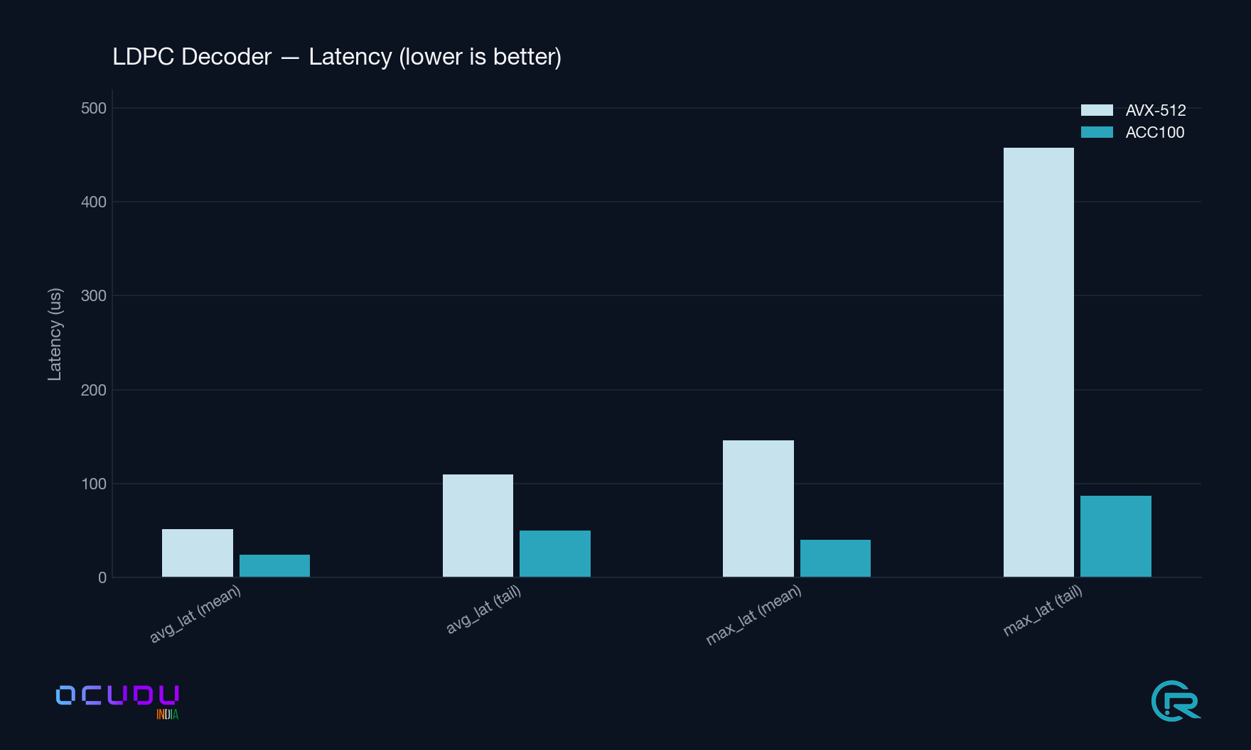
LDPC Decoder avg_latency
51.6 / 109.4 µs
24.5 / 50.1 µs
−53 % (2.1× faster)
LDPC Decoder max_latency
145.9 / 457.7 µs
40.5 / 86.7 µs
−72 % (3.6× better tails)
LDPC Decoder decode_rate
46.6 Mbps
137.4 Mbps
+195 % (2.9×)
PUSCH Processor avg_data_latency
231.9 / 761.5 µs
246.3 / 736.4 µs
+6 % mean, −3 % tail
PUSCH Processor proc_rate
24.0 Mbps
37.4 Mbps
+56 %
LDPC Decoder latency lower is better. The tail-latency gap (rightmost pair) is the headline: 3.6× tighter under ACC100.PDSCH Processor latency lower is better. Tail latency compresses by roughly one third.Throughput higher is better. LDPC decode rate nearly triples; PDSCH and PUSCH processor rates both rise by about half.
7.3 CPU utilisation
Metric
AVX-512 (mean / max)
ACC100 (mean / max)
upper_phy_dl
3.63 % / 22.7 %
4.92 % / 33.9 %
upper_phy_ul
3.79 % / 28.9 %
2.36 % / 15.4 % (−38 %)
ldpc_rm (rate match)
1.30 % / 10.9 %
0.00 % (on accelerator)
ldpc_rdm (rate dematch)
0.13 % / 1.0 %
0.00 % (on accelerator)
The uplink CPU reduction is the headline operational benefit: one core is
freed on the upper-PHY under sustained traffic, allowing either higher
cell counts on the same host or tighter scheduling-latency budgets.
Note on the DL rows. The per-CB ldpc_encoder_* fields on the HW
path reflect batch wall-clock time rather than serialised per-CB compute
time, because ops are submitted to the accelerator in bursts. Use the
PDSCH Processor rows and upper_phy_dl for apples-to-apples DL
comparison those are measured once per TB and are directly comparable.
8. Deployment checklist
Install or confirm DPDK ≥ 22.11 with ACC100 PMD.
Confirm pf_bb_config daemon is running; note its VFIO-VF token.
Bind the ACC100 VF(s) to vfio-pci.
Add the hal.bbdev_hwacc block to the DU YAML (see §4).
Build with ENABLE_PDSCH_HWACC=True and ENABLE_PUSCH_HWACC=True (see §5).
Verify startup log shows intel_acc100_vf and ldpc_enc_q=N ldpc_dec_q=N.
Enable metrics.layers.enable_du_low to observe the per-component LDPC metrics (§6).
Reference blueprints for real deployments from a single edge site to a multi-site operator footprint.
Coming soon. Deployment blueprints are being authored and validated
in OCUDU India lab environments. Feature-specific deployment guidance
that is ready sits under the relevant feature page for example,
Intel ACC100 LDPC offload
has a full deployment checklist.
Planned content:
Single edge-site blueprint one DU, one CU, one core simulator.
Multi-DU aggregation one CU serving multiple DUs (F1 at scale).
Regional deployment multiple edge sites + central CU-CP via Nephio GitOps.
Validated hardware profiles.
Timing and sync, observability, upgrade procedures.
5 - Contributing
How to file issues, propose changes, and submit pull requests to OCUDU India repositories.
Coming soon. The full contributor guide is being written to match
the project onboarding flow. Until it lands, the
Community page lists all the public channels
(mailing list, Slack, TSC meeting) where you can get oriented.
Planned content:
Code of Conduct and DCO sign-off requirements.
How small changes, features, and substantial RFCs flow through review.
Coding conventions per language Go, Python, C++, Helm/Kustomize.
CI expectations and how to run the test suites locally.